3

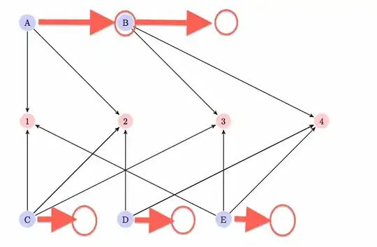
I have this figure with three rows of nodes. I would like to center the first and the third rows by moving the nodes a bit to the right so to make the figure appears more balanced:

enter image description here

I tried with \centering but with no effect.

Here's the code:

\documentclass{paper}

\usepackage{tikz}
\usetikzlibrary{arrows}

\begin{document}

\begin{figure}
\centering
\begin{tikzpicture}[->,>=stealth',shorten >=1pt,auto,node distance=4cm,
  thick]

  \tikzstyle{author node} = [circle,fill=blue!20,right]
  \tikzstyle{thread node} = [circle,fill=red!20,right]

  \node[author node] (1)  {A};
  \node[author node] (2)  [right of=1] {B};

  \node[thread node] (3) [below of=1] {1};
  \node[thread node] (4) [right of=3] {2};
  \node[thread node] (5) [right of=4] {3};
  \node[thread node] (6) [right of=5] {4};

  \node[author node] (7) [below of=3] {C};
  \node[author node] (8) [right of=7] {D};
  \node[author node] (9) [right of=8] {E};

  \path[every node/.style={font=\sffamily\small}]
    (1) edge node {} (3)
    (1) edge node {} (4)
    (2) edge node {} (5)
    (2) edge node {} (6)

    (7) edge node {} (3)
    (7) edge node {} (4)
    (7) edge node {} (4)
    (7) edge node {} (5)
    (8) edge node {} (4)
    (8) edge node {} (6)
    (8) edge node {} (6)
    (9) edge node {} (3)
    (9) edge node {} (5)
    (9) edge node {} (6);

\end{tikzpicture}
\end{figure}

\end{document}
egreg
  • 1,121,712
Francesco
  • 4,624
  • 4
  • 35
  • 66

1 Answers1

2

Loading the positioning library allows better control over relative positioning of nodes. But as your nodes are slightly of different size, I set the on grid option which does reference only the .center anchors of the nodes in the process of the positioning (this means that nodes may overlap).

Circular shapes are furthermore harder to position grid like as their compass anchors are placed on a circle: A circle that fits into a rectangle (square) do have the same .north, .east and so on anchors but not .north east, .south east and so on.

I have used a node distance of 2cm so that the diagram is smaller and thus better to show here. The one occurrence of below right has to be given manual distances so that the vertical part is the same like the current node distance but the horizontal is half the distance.

Code

\documentclass[tikz,class=paper]{standalone}
\usetikzlibrary{arrows,positioning}

\begin{document}
\begin{tikzpicture}[
  node distance=2cm, on grid,
  outer sep=+0pt,
  author node/.style={circle, fill=blue!20},
  thread node/.style={circle, fill=red!20 }]

  \node[author node]              (tA) {A};
  \node[author node, right=of tA] (tB) {B};

  \node[thread node, below=of tA] (c2) {2};
  \node[thread node, left =of c2] (c1) {1};
  \node[thread node, right=of c2] (c3) {3};
  \node[thread node, right=of c3] (c4) {4};

  \node[author node, below right=2cm and 1cm of c1] (bC) {C};
  \node[author node, right=of bC]                   (bD) {D};
  \node[author node, right=of bD]                   (bE) {E};

  \path[-stealth', shorten >=+1pt, thick]
    (tA) edge (c1) edge (c2)
    (tB) edge (c3) edge (c4)
    (bC) edge (c1) edge (c2) edge (c3)
    (bD) edge (c2) edge (c4)
    (bE) edge (c1) edge (c3) edge (c4)
  ;
\end{tikzpicture}
\end{document}

Output

enter image description here

Qrrbrbirlbel
  • 119,821