I'm looking for a way to create a non-rotating persistence of vision device. I have all the electronics set up but I'm stumped with the mechanical design.
I tried these two designs:
But these didn't work so well. Everything shakes violently and it doesn't go nearly as fast as I need (about 20 swipes per second)
Any ideas on how I can build this?
Asked
Active
Viewed 1,735 times
5
shoosh
- 151
- 3
-
Take a look at the details of an automobile's motor, especially at the crank and the plunger. http://en.wikipedia.org/wiki/Piston_motion_equations#Example_graph_of_piston_motion the image below the diagram. – ott-- Jul 01 '13 at 10:55
-
@ott-- this is very similar to the drawing on the left. The problem is that it's very difficult to balance this to run fast. – shoosh Jul 01 '13 at 11:03
-
http://de.wikipedia.org/wiki/Hubkolbenmotor This is a better image (the page is in german, but it's only the image). It's clearly to see why the piston cannot shake around. – ott-- Jul 01 '13 at 11:05
-
@ott-- I mean the whole thing shakes since the rotation is not balanced – shoosh Jul 01 '13 at 11:19
-
You need a more solid base plate of a certain weight. Try 10 kg first. – ott-- Jul 01 '13 at 11:24
-
Is the problem that you want a different mechanism, or that you need help balancing one of the mechanisms you mentioned above? I would imagine that the simplest way to balance these is just to add a dummy arm that's $180^\circ$ out of phase with the first arm. – Ian Jul 01 '13 at 15:48
-
I considered trying to balance it with a symmetric art on the other side but that proved mechanically challenging since there isn't enough place both for the motor and the another arm – shoosh Jul 01 '13 at 21:10
-
@shoosh you are simple getting the hard way to balance this type of mechanism, that's one of the subjects how the continuous rotation is preferred. But even a simple wheel depending on weight, size and speed, will need very precise balancing other wise they will tend to exhibit centrifugal forces so great that can simple "explode" or have big mechanical vibration. Also, with this mechanism, the arm will produce a sinusoidal like speed (considering the wheel at a fixed speed), so it will be more fast in the middle of travel. – Diego C Nascimento Feb 02 '14 at 04:50
2 Answers
3
I'm looking for a way to create a non-rotating persistence of vision device.
It seems to me that the two designs that you propose yourself, at least rely on rotation.
I would suggest getting rid of rotation entirely. In particular since you say you have problems swinging these arms around.
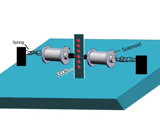
One way to go about this, is by using magnets, springs and electro magnets. Actually, instead of me explaining this, go look at a loud speaker unit, and apply that same principle to your challenge. You want it to move further though, so use some soft springs to suspend your moving component between, so you can get some good range on it.
          <fixed electro magnet>               L
<spring>--<free moving magnet>--<electronics>--E--<spring>
          <fixed electro magnet>               D
The middle line can move from side to side, the electromagnet is curled around the sliding assembly
You would likely need to drive the electro magnet in both directions (reversing the poles) to get some good speed too.
The benefit of this, is that the suspended electronics, can be really light, so you dont need some really heavy weights to keep the vibrations down. And the two springs of either end, could carry the power to the moving electronics.
EDIT:
I got inspired by rocketnagnet's graphics, so i stole some of it, to clarify just a little bit, just to give a hint as to how my ascii graphics was intended.
Zuu
- 131
- 2
2
I think Zuu's answer was very good, but I'd like to add some more detail to it.
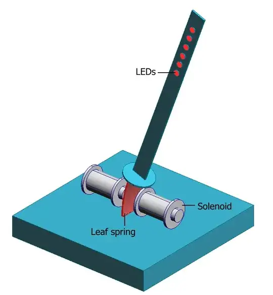
The idea of using a spring is very good. From the start this creates the oscillating movement you want. I would suggest using a steel leaf spring. This is good for two reasons:
- It restricts the movement to just left-right.
- It allows you to add solenoids to drive the movement.
Firstly, set up your spring system. The PCB with LEDs is mounted somehow on the end of the leaf spring. As well as the LEDs, the PCB should also have an accelerometer to measure the movement of the PCB.
Pull back the PCB with LEDs and let it oscillate. Look at the output of the accelerometer to measure the frequency of oscillation. Adjust the length of the spring until the oscillation frequency is about 20 swipes per second.
You're almost there. Now you need to drive the oscillation using the solenoids. Use the accelerometer to synchronise energising the solenoids.
Added:
The reason this is an improvement over Zuzu's answer is that, while solenoids are great for short sharp movements, they are terrible for long smooth movements. The travel you get from them will be too short to make an interesting display.
What you need is some mechanism that allows the solenoids to work over a short distance, while the LEDs move a large distance. Hence allowing the stick to bend at the leaf spring. Whether you consider this to be a 'rotating' mechanism depends on whether you consider bending to be a type of rotating.
Rocketmagnet
- 6,457
- 5
- 29
- 54
-
If your intention here was to "add more detail to Zuu's answer", then i think my answer was misunderstood. The image you show is very similar to the OPs first image, of a bar that rotates around its bottom end. My answer does not have anything rotating about anything. its basically a piston that vibrates back and forth. – Zuu Feb 01 '14 at 17:10
-
I borrowed some of your graphics to give a better hint as to what my idea could look like. – Zuu Feb 01 '14 at 17:39