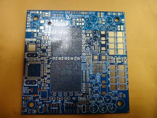
You can use the bare board to "buzz out" the LEDS - using your favourite multimeter in continuity "beep" mode, stick one end on the LED drive sideand then drag it around the FPGA footprints until it pings at you.
You should be able to turn one of them one with a simple HDL file then, using JTAG to first identify the chips so you can build the right bitstream, and then to load the bitstream. If the FPGAs are configured from JTAG programmable flash chips (Altera EPCs) you should be able to load those too. If they are "standard" SPI flash devices, that'll be a bit more buzzing out to do once you've identified them.
Anything else will require a clock. Find a crystal oscillator on the board and bozz that out to the FPGA pins.
You should then be able to make an LED flash (the "hello world" of FPGA land!).
Buzzing out the Rx and Tx lines from the FTDI chip should then get you a potential terminal. From there it should be dead easy (!)
OK, so without a bare board to help...
There is JTAG software which can scan the chain and tell you which signals are high and low, or drive individual pins high and low. This is commercial: http://www.topjtag.com/probe/ - I'm sure there is some non-commercial open-source somewhere too, but can't find it at the moment.
You should be able to use this to step through all of the FPGA pins and find which one lights up the LEDs.
Putting an LED on the FTDI Rx and Tx pins, you should be able to light them up too, or make them go off if they are floating high.
The same should also work for the crystal I imagine too.
You'll be creating contention on each signal which is actually driven from the non_FPGA end each time you step through, but for short periods (even seconds) that should be fine.