14

It is rather well-known that, with VGA-compatible PC video adapters, in black-and-white text modes video memory is available at linear address 0xB0000, in colour text mode at address 0xB8000, while in graphics mode, it appears at address 0xA0000. Ralf Brown’s has a whole table showing which video modes use which segment bases.

It seems it would have been simpler to always place the video memory at the same address. Indeed, this design created some complications when a protected-mode video ROM interface was created; an operating system had to allocate three selectors to video memory to use it, instead of just one.

What is the reason for the changing memory mapping that we ended up with? Was it a deliberate design that served a useful purpose, or purely an accident, a compromise between an attempted do-over and backwards compatibility?

user3840170
  • 23,072
  • 4
  • 91
  • 150
  • Is the video memory stored in the CPU's RAM or are those addresse memory maped to RAM of the GPU? – zomega Feb 07 '24 at 13:51
  • 3
    @zomega the addresses map to memory on the display adapter. – Stephen Kitt Feb 07 '24 at 13:54
  • 1
    Back in the 90s, I wrote a system that used both a Hercules graphics card and an EGA graphics card, so we could show 2 displays (one at either end of a conveyor). It was useful then. – Neil Feb 08 '24 at 15:10
  • @zomega While Stephen's comment is, of course, accurate I think it's worth adding that a display adapter was (initially) a circuit board with a quantity of memory that (usually) appeared in the CPU's memory map. Depending on the mode, a word of this memory represented one or more characters or pixels. There were of course exceptions, like at least one NEC7220-based board made by Leanord on France. – Mark Morgan Lloyd Feb 08 '24 at 19:48

3 Answers3

26

The history behind the various base addresses is as follows:

  • the area starting at A0000h was set aside for video frame buffers in general (see Who set the 640K limit?)
  • MDA used 4KiB starting at B0000h (out of 16KiB reserved, and 32KiB occupied in practice because of partial address decoding in the MDA)
  • CGA used 16KiB starting at B8000h (see also Who decides what is the memory address that the CGA video buffer will be mapped to?)
  • EGA introduced modes based at A0000h, using planes of up to 64KiB, depending on the amount of memory installed; this wasn’t backward-compatible with MDA or CGA, so a new address was chosen

I don’t know why the MDA and CGA base addresses were chosen in the B0000h bank rather than A0000h; but there is a useful side-effect to the choice: MDA and non-MDA modes can be used in parallel, which enables dual-monitor setups. Thanks to the non-overlapping display buffers, and to the non-overlapping I/O port ranges (3B0h–3BBh for MDA, 3D0h–3DFh for CGA; EGA adds 3C0h–3CFh), a variety of combinations are possible, starting with CGA and MDA in the original IBM PC (John Elliott’s “Dual-Head Operation on a Vintage PC” gives details). “Common” uses of this feature included displaying a running program on the colour screen and a debugger on the monochrome screen (even under Windows), or a CAD render on the colour screen and UI on the monochrome screen.

Aside from dual-monitor use, the combination of features provided on the MDA and CGA required different ports and memory addresses to be used. On PCs at the time, there was no central coordination of address assignment; each card in the system was equal on the bus, for both memory addresses and I/O ports, and chose which addresses it responded to. The original MDA also included a parallel port; even if dual displays weren’t envisioned, users buying a PC with MDA and later installing CGA might want to keep their MDA to connect their printer. If the MDA and CGA buffers or port ranges overlapped, the system wouldn’t behave correctly; it was probably simpler to map the adapters to separate ranges rather than add jumpers to choose which card “owned” the relevant addresses (as seen on EGA).

Dual-monitor use seems to have been an intentional decision; at least, it is mentioned in the original IBM PC Technical Reference, in the DIP switch settings for monitor type selection (the MDA setting is listed as “IBM monochrome display or both types of display adapters”; PCs with dual monitors used the monochrome monitor as their primary display). The comments on dual-adapter purchases in the internal IBM PC Q&A suggests that simultaneous dual-monitor use wasn’t a well-known feature however, at least not in 1981. Since the MDA also hosted the parallel port, PCs with both MDA and CGA weren’t unheard of, but most CGA-equipped PCs would only have a single, colour, monitor (and switches configured for CGA-only operation). (A separate card providing only a parallel port was also available.)

Bear in mind that the PC wasn’t really designed as a family of computers, and didn’t have an expansion-ready high-performance API of any kind, so many of its implementation details became features, simultaneously sub-optimal and locked-in for a long time.

Stephen Kitt
  • 121,835
  • 17
  • 505
  • 462
  • +1 You beat me again :)) Little point, A0000h was unassigned at first, B000h was the designated video segment. A0000h only came into play as the EGA needed more memory in addition to the 64 KiB at B0000h. C0000h was chosen for video-BIOS – Raffzahn Feb 07 '24 at 12:01
  • @Raffzahn the IBM PC Technical Reference mentions 128KiB reserved at 640KiB (A0000h) for “graphic/display buffer”. – Stephen Kitt Feb 07 '24 at 12:11
  • Sure about that? I remember that there were changes between the original Technical Reference and later (after 10/1982) editions. Might need to go upstairs. – Raffzahn Feb 07 '24 at 12:17
  • The August 81 edition says “128KB RESERVED GRAPHIC/DISPLAY BUFFER” starting at 640KiB in the memory map on page 2-25; the next page doesn’t quite match that, but still sets aside much more than the 32KiB block starting at B0000h (A0000h reserved, A4000h–BFFFFh graphic/display buffer). – Stephen Kitt Feb 07 '24 at 12:25
  • 1
    Found it as well. Yes, it's that change I had in mind. 4/83 edition changed that drawing. Updated my answer to reflect this. Thanks. (Also, yes, dual monitor use was intended and supported by at least one IBM terminal emulation package.) – Raffzahn Feb 07 '24 at 12:32
  • I edited correct memory sizes into your post. There is another reason for the EGA graphics modes to be at A000: Mode 0Fh (640x350 mono) and 10h (640x350 color) are very similar. Mode 0F could be used with a CGA installed at the same time and Mode 10 could be used with an MDA installed at the same time. Using a new base that doesn't conflict with either makes a lot of sense - in addition of getting the 64K address space required to deal with banks/planes of up to 64K. – Michael Karcher Feb 07 '24 at 22:52
  • Thanks @MichaelKarcher! Good point re mode 0F, it is quite a neat feature. – Stephen Kitt Feb 08 '24 at 08:43
  • "CAD render on the colour screen and UI on the monochrome screen."... where the UI of things like AutoCAD was initially interactive text rather than menus etc. – Mark Morgan Lloyd Feb 08 '24 at 19:52
  • If I had two monitors, I would have expected it more likely they are both the same type, instead of two different types. But maybe that's from today's perspective. – Paŭlo Ebermann Feb 09 '24 at 00:45
14

TL;DR: Compatibility

Before VGA there was MDA, CGA and EGA and it's all about continued support.

But Why Different Memory Regions ?

Video in the IBM PC is based on video cards bringing their own memory. While it is mapped into CPU address space, Video access can only happen from the card itself. Thus avoid CPU side collisions (bus war) when operating more than one card, they had to use different address regions.

Was it Intended to Have More Than One Parallel?

Sure. While the on-board BIOS did only support one card at a time, the Technical Reference does note that configurations of MDA plus CGA are intended, for example on page 1-125 regarding initialisation:

enter image description here (IBM PC technical Reference 4/1983 p.1-125)

Or when it's about switch settings needed for the BIOS startup when MDA and another Adapter is installed. This ensures that the BIOS will use MDA as default.

enter image description here 
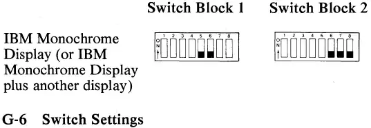
(IBM PC Technical Reference 4/1983 p.G-6)

Is It Useful?

Oh yes. Developers loved to have two screen setup, one for the application and a second one for debugging. Some debuggers did support the setup quite well. But the same goes for application software, where offering use of a second screen was one of the advantages the IBM had over other systems of the same time.

Development History

IBM reserved the space above A0000h for extensions, with 128 KiB at A000h reserved for Video (*1). In the beginning, with the 1981 PC, two cards with 16 KiB video RAM each were offered. They got each assigned half the 64 KiB address space:

  • MDA starting at B0000h
  • CGA starting at B8000h

While both could feature the same memory layout, having them at different address enabled parallel use (*2). Later EGA (1981) was added with the PC-AT. Beside emulating MDA and CGA at their respective addresses, it also offered new video modes needing a continous 64 KiB buffer. To facilitate this, while still allowing parallel use of a second screen with MDA or CGA (or both), it needed a new base address:

  • EGA starting at A0000h

This meant that the originally reserved 16 KiB at A0000h were now assigned as buffer(*3), thus the video-BIOS ROM needed for operating the EGA had to be placed else were. 32 KiB at C0000h was chosen for this. Which also adds an issue for use of EGA cards in PCs, as only the October 1982 BIOS added a ROM search at C0000h.

VGA in turn simply inherited the address layout for compatibility.


*1 - More exact, 16 KiB at A0000h reserved and 112 KiB starting at A4000h for video buffer. One may guess that the first 16 KiB were intended for usage by ROM extension. See page 2-27 of the first (8/81) edition of the PC Technical Reference.

*2 - All of that being a constrain of each card bringing it's own video memory.

*3 - See page 1-14 of the April 1983 Technical Reference.

Raffzahn
  • 222,541
  • 22
  • 631
  • 918
6

For CGA vs. MDA, the reasoning for using different base adresses is simple and obvious: These two video systems are designed to co-exist for dual-monitor solutions thus each need a unique memory range.

When VGA was introduced, IBM apparently wanted to continue support the dual-mode setup, so VGA had to occupy yet another distinct address. IBM's original VGA card could co-exist with the MDA card as well

tofro
  • 34,832
  • 4
  • 89
  • 170
  • You must mean EGA when you write VGA? VGA is based on EGA and VGA was not originally even a card like EGA was, but integrated on motherboard. EGA was a card and after VGA was introduced, it was only later available on a card. – Justme Feb 07 '24 at 12:13
  • I suspected something like this, but have you got any materials showing that multi-adapter systems were an explicitly supported setup? – user3840170 Feb 07 '24 at 12:17
  • @user3840170 Supported setup by whom, and what kind of material? It was pretty common. IBM PC 5150 allowed you to have both CGA and MDA in the system. And people developing e.g. games used VGA for actual display and MDA or Hercules as the monochrome adapter for debugging. – Justme Feb 07 '24 at 12:23
  • 1
    @user3840170 it is mentioned in the original technical reference, see my answer. – Stephen Kitt Feb 07 '24 at 12:31
  • And "MODE MONO" and "MODE CO80" are good examples where even DOS supported multiple monitors. – tofro Feb 07 '24 at 15:12
  • @tofro It's not really DOS that supported multiple monitors. All those MODE commands do is to force the BIOS data area equipment flags to indicate the display type currently present in the system, like it was read from 5150 motherboard jumpers during bootup. The DOS console driver will still just call the BIOS video routines as usual, the BIOS video routines just then write to MDA or CGA card based on the equipment flags. – Justme Feb 07 '24 at 15:30
  • @Justme Of course it's DOS - That's nitpicking. You wouldn't say "DOS doesn't support file reading, because that is done by the BIOS". Without the MODE command you couldn't switch. – tofro Feb 08 '24 at 00:49
  • 1
    @user3840170 Look at the DIP configuration instructions for the IBM EGA card: It explains how to set the switches if a second card is present or not. Furthermore, the assignment of different memory and I/O ranges is a strong indication that hardware support for a dual video-card setup was already considered before the PC hit the market. Note that neither card satisfies all requirements at that time: The MDA card couldn't display any kind of graphics beyond ASCII/CP437 art, and the CGA card couldn't display text at decent quality (because of TV compatibility). – Michael Karcher Feb 08 '24 at 07:00
  • @MichaelKarcher Well, the lack of graphics capabilities of MDA was what the Hercules monochrome cards aimed at (with great success) using the same memory ranges. – tofro Feb 08 '24 at 09:13