Filters.
A filter is a circuit which is designed to react differently depending on the frequency. Every real (not mathematically ideal) circuit element does this to some degree, but filters are designed to have a very specific frequency response.
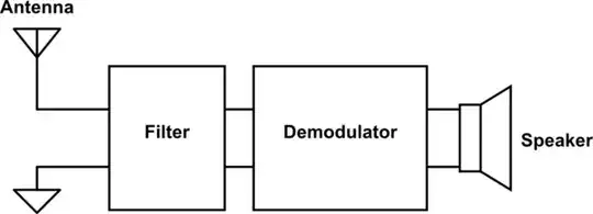
Here's a very loose and incomplete high-level schematic of a simple radio receiver:
simulate this circuit – Schematic created using CircuitLab
As you can see, the filter has four terminals: two for the input from the antenna, and two for the output to the demodulator. (In practice, they might more likely share a single ground bus for both input and output sides, for a total of three terminals.)
The effect of the filter is that the part of the signal coming from the antenna which has the desired frequency passes through — as if the wires on the left were connected to the wires on the right — and the rest of it does not — as if the wires on the left were either shorted together or disconnected.
Filters can be made out of various components, but most commonly inductors and capacitors. Introductions to electronic circuits often say something like “capacitors pass AC and block DC; inductors block AC and pass DC". This is true, but simplified; there is not just “AC” but the entire spectrum of possible frequencies, and the higher the frequency the more the capacitor will pass it and the inductor will block it. If you put an inductor and capacitor in parallel or in series, you get a circuit with a resonant frequency — a specific frequency (actually a small range of frequencies) which it will pass (or block) much more than other frequencies. That's the simplest filter. Additional complexity in filter design gets you "sharper" filters that are better at passing what you want and blocking what you don't want.
In addition, the antenna itself has frequency-varying characteristics and therefore acts as a filter. This is why there are different size antennas for different frequency ranges.
The above is a very simple picture. The main thing that I've omitted (besides e.g. amplifiers, which every radio but a “crystal radio” has in order to produce an audible output volume) is tuning.
One approach to tuning is to adjust the filter's resonant frequency (or passband) to the frequency you want to receive. Early receivers (see crystal radio and tuned radio frequency (TRF) receiver) did use this technique. However, it is difficult to make a filter that is both adjustable and sharp enough to be good at receiving one station and not also an adjacent one (it has poor selectivity).
Instead, modern radios (starting with the superheterodyne design) internally generate a signal at a particular offset from the desired frequency (the local oscillator (LO)) which is combined with the signal from the antenna (mixed) in such a way as to produce a copy of the radio signal at a fixed frequency (intermediate frequency (IF), equal to the offset between the LO and the input) which is then filtered using a sharp non-adjustable filter before being passed to the demodulator.
Originally, the local oscillator was an adjustable filter (usually containing a variable capacitor and a fixed inductor) and amplifier connected in a positive feedback loop — the filter selects the particular frequency and the amplifier keeps the signal oscillating. (Here, the filter doesn't need to be especially sharp because it's handling only the fed-back signal — which will quickly settle on only the resonant frequency.) Modern radios instead use digital circuits to generate the local oscillator signal, via digital-to-analog converters (DAC) and phase-lock loops (PLL); this allows very precise tuning under computer control.