I don't know if this counts as "easy", but:
- Find the series resonant frequency. Multiply this frequency by $2\pi$ to convert it to an angular frequency, and call that $\omega_s$.
- Note the resistance at this frequency. That's $R$.
- Find the parallel resonant frequency, multiply by $2\pi$, and call it $\omega_p$.
- Halfway between these resonant frequencies is $\omega_t$. Measure the impedance there and call it $Z_t$.
- Calculate the remaining values:
$$ C_p = \mathrm{Re} \left(
i (\omega_s^2 - \omega_t^2)
\over
\omega_t Z_t (\omega_t^2 - \omega_p^2)
\right) $$
$$ C_s = {C_p (\omega_p^2 -\omega_s^2) \over \omega_s^2} $$
$$ L = {1 \over C_s \omega_s^2} $$
These are derived below as equations 13, 7, and 2.
If you can measure $C_p$ some other way, then you can skip the measurement at $\omega_t$ and just use the latter 2 of these equations and the resonant frequencies.
Another method is to measure the series resonant frequency with some variable capacitance in series. This might result in some simpler math, and it doesn't require a VNA: only a sweep generator and a power detector.
Explanation:
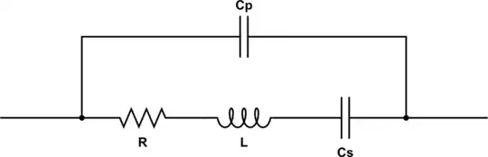
simulate this circuit – Schematic created using CircuitLab
The impedance of this circuit is:
$$ Z(\omega) = \left({1 \over -i/(C_s\omega) + i L \omega + R} + i C_p \omega \right)^{-1} \tag 0 $$
When $L$ and $C_s$ have reactance equal in magnitude but opposite in sign, we are very close to series resonance. I say close because $C_p$ has some effect, but it's small because the impedance of the lower components is very much lower. The error is about 0.25 Hz for the 14 MHz crystal in the video. If we neglect that error, the math is simpler.
Let's define $\omega_s$ as the series resonant angular frequency. We can then solve this equation for $C_s$ or $L$.
$$ i \omega_s L = -{1 \over i \omega_s C_s} \tag 1 $$
$$ L = {1 \over C_s \omega_s^2} \tag 2 $$
$$ C_s = {1 \over L \omega_s^2} \tag 3 $$
The series resonance can be found by the VNA by looking for a frequency where reactance is zero and resistance is on the order of 10 ohms. At this frequency, $R$ is the only significant impedance, so:
$$ Z(\omega_s) = R \tag 4 $$
Parallel resonance occurs when the admittance of the two parallel branches of the circuit are equal. Again we're going to accept a little bit of error to simplify the math by neglecting the influence of $R$. Let's call the parallel resonance angular frequency $\omega_p$:
$$ i\omega_p C_p = - \left(
i\omega_p L
+ {1 \over i\omega_p C_s}
\right)^{-1} \tag 5 $$
Substitute equation 2 for $L$ and simplify:
$$ i\omega_p C_p = - \left(
{i\omega_p \over C_s \omega_s^2}
+ {1 \over i\omega_p C_s}
\right)^{-1} $$
$$ i\omega_p C_p = - \left(
{i^2 \omega_p^2 \over i\omega_p C_s \omega_s^2}
+ {\omega_s^2 \over i\omega_p C_s \omega_s^2}
\right)^{-1} $$
$$ i\omega_p C_p = - \left(
{i^2 \omega_p^2 + \omega_s^2 \over i\omega_p C_s \omega_s^2}
\right)^{-1} $$
$$ i\omega_p C_p = - \left(
{i\omega_p C_s \omega_s^2 \over \omega_s^2 - \omega_p^2 }
\right) $$
$$ i\omega_p C_p =
{i\omega_p C_s \omega_s^2 \over \omega_p^2 - \omega_s^2 }
$$
$$ C_p = {C_s \omega_s^2 \over \omega_p^2 -\omega_s^2 } \tag 6 $$
$$ C_s = {C_p (\omega_p^2 -\omega_s^2) \over \omega_s^2} \tag 7 $$
Just one more degree of freedom to solve for. Pick some angular frequency that isn't resonant, call it $\omega_t$. The impedance measured at this frequency is $Z_t$. From equation 0, we can write:
$$ Z_t = \left({1 \over -i/(C_s\omega_t) + i L \omega_t + R} + i C_p \omega_t \right)^{-1} $$
Substitute equations 2 and 6 for $L$ and $C_p$:
$$ Z_t = \left(
{1 \over -i/(C_s\omega_t) + i {1 \over C_s \omega_s^2} \omega_t + R}
+ i {C_s \omega_s^2 \over \omega_p^2 -\omega_s^2 } \omega_t
\right)^{-1} \tag 8 $$
Now there is only one variable that can't be measured directly by the VNA: $C_s$. If we can solve for $C_s$ we're golden.
Unfortunately the solution is very hairy. But it gets substantially simpler if we ignore $R$:
$$ C_s = {
i(\omega_p^2 - \omega_s^2)(\omega_s^2 - \omega_t^2)
\over
\omega_s^2 \omega_t Z_t (\omega_t^2-\omega_p^2)
} \tag 9 $$
Of course, this is going to give you a complex number, and you can't really have a complex-valued capacitor. But we can gloss over that! Just ignore the complex part. As long as we pick a frequency where $R$ isn't too significant, the error will be small.
Halfway between the series and parallel resonant frequencies seems to work pretty well.
Addendum: it's also possible to start with equation 5 and substitute equation 3 for $C_s$ instead. I wonder if that leads to a simpler solution:
$$ i\omega_p C_p = - \left(
i\omega_p L
+ {1 \over i\omega_p {1 \over L \omega_s^2}}
\right)^{-1} $$
$$ i\omega_p C_p = - \left(
i\omega_p L
+ {L \omega_s^2 \over i\omega_p}
\right)^{-1} $$
$$ i\omega_p C_p = - \left(
{i^2\omega_p^2 L + L \omega_s^2 \over i\omega_p}
\right)^{-1} $$
$$ i\omega_p C_p = -
{i\omega_p \over i^2\omega_p^2 L + L \omega_s^2}
$$
$$ i\omega_p C_p = -
{i\omega_p \over L (\omega_s^2 - \omega_p^2)}
$$
$$ C_p =
{1 \over L (\omega_p^2 - \omega_s^2)}
\tag{10}
$$
$$ L =
{1 \over C_p (\omega_p^2 - \omega_s^2)}
\tag{11}
$$
Now we can express the impedance in terms of $L$ with substitutions from equations 10 and 3:
$$ Z_t = \left(
{1 \over -i L \omega_s^2 / \omega_t + i L \omega_t + R}
+ {i \omega_t \over L (\omega_p^2 - \omega_s^2)}
\right)^{-1} $$
Which is still pretty bad unless $R$ is dropped:
$$ L = {
i \omega_t Z_t (\omega_p^2 - \omega_t^2)
\over
(\omega_p^2 - \omega_s^2)(\omega_s^2 - \omega_t^2)
} \tag{12} $$
Or, we can do the same thing for $C_p$ with equations 11 and 7:
$$ Z_t = \left(
{
1
\over
-i/\left({C_p (\omega_p^2 -\omega_s^2) \over \omega_s^2}\omega_t\right)
+ {i \omega_t \over C_p (\omega_p^2 - \omega_s^2)} + R
}
+ i C_p \omega_t
\right)^{-1} $$
$$ Z_t = \left(
{
1
\over
{-i \omega_s^2 \over \omega_t C_p (\omega_p^2 -\omega_s^2)}
+ {i \omega_t \over C_p (\omega_p^2 - \omega_s^2)} + R
}
+ i C_p \omega_t
\right)^{-1} $$
$$ Z_t = \left(
{
1
\over
{-i \omega_s^2 + i \omega_t^2 \over \omega_t C_p (\omega_p^2 - \omega_s^2)}
+ R
}
+ i C_p \omega_t
\right)^{-1} $$
$$ Z_t = \left(
{
1
\over
{i (\omega_t^2-\omega_s^2) \over \omega_t C_p (\omega_p^2 - \omega_s^2)}
+ R
}
+ i C_p \omega_t
\right)^{-1} $$
Still hairy, unless again removing $R$:
$$ Z_t = \left(
{\omega_t C_p (\omega_p^2 - \omega_s^2) \over i (\omega_t^2-\omega_s^2)}
+ i C_p \omega_t
\right)^{-1} $$
$$ C_p Z_t = \left(
{\omega_t (\omega_p^2 - \omega_s^2)
\over i (\omega_t^2-\omega_s^2)}
+ i \omega_t
\right)^{-1} $$
$$ C_p Z_t = \left(
{\omega_t (\omega_p^2 - \omega_s^2) + i^2 \omega_t (\omega_t^2-\omega_s^2)
\over i (\omega_t^2-\omega_s^2)}
\right)^{-1} $$
$$ C_p Z_t = {
i (\omega_t^2-\omega_s^2)
\over
\omega_t (\omega_p^2 - \omega_s^2) - \omega_t (\omega_t^2-\omega_s^2)
} $$
$$ C_p Z_t = {
i (\omega_t^2-\omega_s^2)
\over
\omega_t (\omega_p^2 - \omega_s^2 - (\omega_t^2-\omega_s^2))
} $$
$$ C_p = {
i (\omega_s^2 - \omega_t^2)
\over
\omega_t Z_t (\omega_t^2 - \omega_p^2)}
\tag {13} $$
This is a little better!
I threw together an ugly script to check the math, using the values from W0QE's video, and the numbers seem to add up.