9

I have created a fairly simple TDOA system that uses ultrasonic signals emitted from two speakers to geolocate (relative to the speakers) mobile phones. The two signals are separated by frequency.

The system has the following constraints:

  • The signals must be inaudible. To that end we stick to frequencies above 17 kHz. A few people can still hear that, but most can't.
  • Sample rate is 44.1 kHz.
  • Music will typically be playing, so there is lots of interference at the lower frequencies.
  • We don't have control over how well the speakers and microphones work at the upper frequencies, so we've kept our upper limit at around 20 kHz.

The particular signal that I am using is BPSK modulated 13-bit Barker codes because of their good autocorrelation properties. The autocorrelation looks like the following- Signal autocorrelation

When I cross-correlate the expected signal against the received signal in real life, though, what I get typically looks like this- Typical cross-correlation

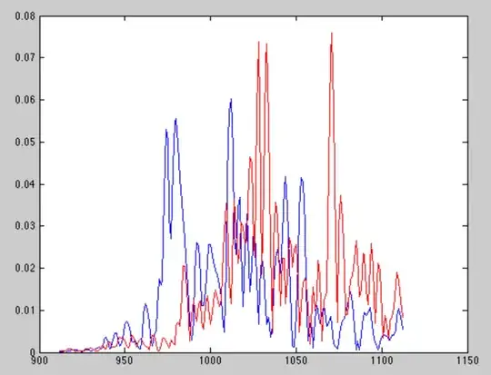
The blue is the cross correlation with the speaker 1 signal, and the red is the cross-correlation with the speaker 2 signal. It appears that the echoes are significant and, unfortunately, often stronger than the direct path signal due to the directional gain of the microphone.

I tried simply detecting the earliest appearance of the signal as that is likely to be the direct path. This approach is very sensitive to the threshold that I use for deciding when the signal is present and so is not robust at all.

I would like a robust approach for determining the "true" arrival time of the signal- i.e. the arrival time of the direct path signal. Perhaps some form of channel estimation and deconvolution? If so, how would that work?

Data/Code: I want to make it clear that I am not expecting anyone to analyze the data or inspect my code. I have made them available in case you want to do so. I am mostly interested in ideas.

I made the raw received signal and modulated expected signals available for download. They are all sampled at 44.1 kHz. Correlating the received signal with the expected signals will produce something similar but not identical to the picture above because I move the received signals to baseband and decimate before correlating with the expected signals.

Received signal

Expected signal #1

Expected signal #2

Matlab scripts The Matlab scripts has both the signal generation script (genLocationSig.m) and my receive/processing script (calcTimingOffset.m).

Jim Clay
  • 12,101
  • 31
  • 55
  • Is it possible for you to share your rx1, rx2, and template data? – Tarin Ziyaee May 07 '14 at 14:21
  • @user4619 I will try to do that this evening. – Jim Clay May 07 '14 at 16:31
  • Real quick: I received your data and produced a contrast-enhanced STFT-PSD. I am guessing those 5 blips at the bottom are your two signals, separated by frequency. It appears like your signals are being transmitted ok, but I do not believe echos or multipath are your problem. As you can see there is a lot of intermittent (broadband) noise between the pulses, at least in the beginning. If you complex band shift, downsample, correlate with your barker sequence, and look at the envelope, what are you seeing? – Tarin Ziyaee May 08 '14 at 16:35
  • @user4619 You are correct, those are the two pulses. When I demodulate, filter, and correlate I get correlations like the one shown in the post above. I don't remember which of the pulse sets I got that picture from, but it was one of them. – Jim Clay May 08 '14 at 19:08
  • 1
    Ok, a couple things: I) have you considered using a linear-chirp instead of coded waveforms such as this? You have a lot more flexibility with them, and there are drastically less moving parts involved. II) What, if any, are your bandwidth constraints? For example your templates appear to be about 1 KHz wide, any reason for this? Can you go higher? With a linear-chirp this is easy. III) While I doubt there is anything wrong with your demodulation, putting it up would help. That, and it would save me the trouble of writing it! – Tarin Ziyaee May 08 '14 at 19:39
  • As far as the methods that may help you here, if you want to stick to Barker waveforms, consider simply coding up more than 1 bit. I am assuming that you are simply coding up 1 bit right now, and sending that over. If you instead send, say, 100 random bits over, you would get further processing gain. You would correlate each bit down, and then correlate the bits themselves. – Tarin Ziyaee May 08 '14 at 19:44
  • (continued): But again, like the previous comment, I do not know what your constraints are. Actually, if you do this scheme, you can then use an LSE channel estimator to find the start of the sequence. More on your constraints are needed though, it would be good if you commented on them. – Tarin Ziyaee May 08 '14 at 19:45
  • @user4619 I'm encoding all 13 bits of the Barker code, not just one bit. I'm not against using a chirp, except that when you factor in doppler frequency offsets the auto-correlation is not good. An exponential chirp might be interesting, but I don't think it would be any better against echoes. I'll update my question this evening based on your comments. – Jim Clay May 08 '14 at 20:33
  • 1
    Regarding the bit comments, there is misunderstanding: Let us call each 1 of the 13 states of the barker code a 'chip'. So if I transmit a bit, I am transmitting 13 chips. If I transmit 2 bits, I am transmitting 26 chips, etc etc. So my question was, how many bits are you transmitting? I am assuming you are just transmitting 1 bit, and so I am saying you may also consider transmitting a lot more, to beef up your coding gain. Does that make sense? – Tarin Ziyaee May 08 '14 at 21:18
  • @user4619 I see. Then yes, by that terminology the signals are 1 bit. I have considered sending multiple bits and still might. I haven't to this point mostly because of the autocorrelation ambiguity that would introduce. We would have a big center spike and two half-size spikes, one on either side at a distance of the barker code length. – Jim Clay May 09 '14 at 12:18
  • Why Barker codes? You aren't transmitting data using them, are you? They're just beacons? I think something longer with less "perfect" autocorrelation will actually give better results because of its length. Also your signal needs to be distortion-resistant if you're playing it out of a speaker. Chirp-like signals work better for that. Should it still track the phones while they're moving? Noise-like signals will disappear during Doppler shift. http://www.ijser.org/researchpaper%5CEMPIRICAL-ANALYSIS-ON-DOPPLER-TOLERANT-RADAR-CODES.pdf – endolith May 09 '14 at 18:48
  • Though also, speaker distortion can turn ultrasound into audible sound, and I think the results of noise-like signals would be less perceptible than chirp-like signals? – endolith May 09 '14 at 19:05
  • @endolith No, I'm not transmitting data with them. The entire point of the Barker codes is to determine when they arrive. That's an interesting point about chirps being more distortion resistant. I'm not worried about doppler making the signals audible because the people will be on foot (think concerts and the like), and the speakers will not be moving. If they are waving their phones around that can cause some doppler, but just for the phone itself. – Jim Clay May 09 '14 at 20:38
  • @endolith I'm open to using longer signals if that will work better. I just don't want to get false positives from the autocorrelation "sub-spikes" of other sequences. I guess for longer sequences the sub-spikes aren't very big. And yes, it would be nice to get robust results with doppler (again, waving the phone around), but getting a non-result would be okay too. – Jim Clay May 09 '14 at 20:40
  • @JimClay: I didn't mean that doppler makes the signals audible, I meant intermodulation distortion in the speaker could. and Doppler will happen any time the phones are moving relative to the speakers, so if you're tracking moving people walking around, it needs to be resistant to that. I'm not sure what signals are doppler-resistant and also not correlate with each other, but they probably exist. I guess chirps with non-overlapping start and stop frequencies would be the most obvious example. Maybe look into the signalling GPS uses? – endolith May 10 '14 at 15:50
  • Did you see this? Indoor Pseudo-ranging of Mobile Devices using Ultrasonic Chirps It uses ultrasonic chirps out of off-the-shelf speakers with different chirp rates to separate different speakers. – endolith May 16 '14 at 20:39
  • @endolith No, I hadn't. Thanks for the link. – Jim Clay May 16 '14 at 21:05
  • https://www.google.com/search?q=inaudible+tdoa+speaker finds other relevant things – endolith May 16 '14 at 21:20

1 Answers1

3

These are not the codes you are looking for...

As I mentioned in the comments, there are quite a number of ways to do robust TDOA. (Cross-correlation with Linear Chirps, Exponential Chirps, and CDMA-type methods). You have already built a TDOA system utilizing codes, (and that is indeed a good choice over linear-chirps if you need robustness to doppler), however you are limiting yourself artificially in two ways:

  • Barker codes only go up to length $13$. We can however make PN-sequence codes of arbitrary length to get a lot more coding gain.
  • The use of only $1$ bit in your transmission. We can encode an entire preamble of many bits to transmit, gaining further resilience to multipath.

Use a PN-Sequence:

Thus, very simply, change the codes you use to modulate your carrier by: Use PN-Sequences instead. PN generated codes can be of (nearly) arbitrary length, and can be generated via LFSRs. (They also go by the name 'whiteners' in some texts). Here are three PN-sequences of length $31$, $61$, and $127$ respectively.

PN_31 = [ 1  1 -1 -1  1  1 -1  1 -1 -1  1 -1 -1 -1 -1  1 -1  1 -1  1  1  1 -1  1  1 -1 -1 -1  1  1  1];

PN_61 = [ 1  1  1 -1  1  1 -1  1 -1 -1  1 -1 -1  1  1  1 -1 -1 -1  1 -1  1  1  1  1 -1 -1  1 ...
     -1  1 -1 -1 -1  1  1 -1 -1 -1 -1  1 -1 -1 -1 -1 -1  1  1  1  1  1  1 -1  1 -1  1 -1 ...
      1  1 -1 -1  1  1 -1];

PN_127 = [-1     1     1     1    -1     1    -1    -1     1    -1     1     1    -1    -1    -1     1     1    -1     1     1     1     1    -1     1     1    -1     1    -1 ...
       1     1    -1     1     1    -1    -1     1    -1    -1     1    -1    -1    -1     1     1     1    -1    -1    -1    -1     1    -1     1     1     1     1     1 ...
      -1    -1     1    -1     1    -1     1     1     1    -1    -1     1     1    -1     1    -1    -1    -1     1    -1    -1     1     1     1     1    -1    -1    -1 ...
       1    -1     1    -1    -1    -1    -1     1     1    -1    -1    -1    -1    -1     1    -1    -1    -1    -1    -1    -1     1     1     1     1     1     1     1 ...
      -1     1    -1     1    -1     1    -1    -1     1     1    -1    -1     1     1     1];

The circular and linear auto-correlations of the sequences are shown below. They will clearly yield white spectra, but more than that, we are no longer limited to $13$ chip lengths. In fact, the last code, PN_127, yields a coding gain of $10 \ log [\frac{127}{13} ] \approx 10$ dB gain over the barker sequence, all the while guaranteeing white spectra.

enter image description here

Transmit a preamble:

In your particular application, you mentioned that you were only transmitting one bit. You should try to avoid this if you can help it, and transmit as many bits as your application can allow, to get further coding gain out.

This is what is commonly done on communication protocols to align with the beginning of a packet. A (known) preamble is transmitted, composed of many bits. Each bit, is composed of many chips. (In our example, $31$, $61$, or $127$ chips with either of the above PN codes). Lastly, the bit sequence itself can be composed of yet another PN sequence, or if you like, you may transmit $13$ bits composing a barker pattern, with each bit being composed of either one of the the above PN sequences.


Try one or both of those solutions, and put up your results. I expect there to be tangible improvements that we can then iterate on. (Pulse shaping, different/longer PN sequences, etc).

Tarin Ziyaee
  • 2,831
  • 16
  • 14
  • 1
    Yes, I plan on trying longer sequences. I did not know that the circular autocorrelations of pn sequences were so nice- interesting. Unfortunately for my application it is the linear autocorrelation that matters. Regarding the preamble- the entire sequence is, in a way, a "preamble", in the sense that what makes a preamble useful is that it is a known data pattern. My entire signal is known a priori. – Jim Clay May 13 '14 at 20:28
  • I've decided to go a little overkill on the signal length by using an order 10 lfsr (1023 chips) to either prove or rule out that the problem is solvable by lengthening the signal. I'll post what happens. – Jim Clay May 13 '14 at 20:29
  • @JimClay Excellent. Yes, for an application like this, PN-sequences are your friend. And also yes, use more than 1-bit if you can. Definitely post your results! (Please use @ to ping me so I know when you have something new). – Tarin Ziyaee May 13 '14 at 20:36
  • I need to do some more testing, but it appears that a longer pn sequence will work. – Jim Clay May 16 '14 at 12:35
  • 1
    @JimClay Glad to hear that. Im curious to see what the received xcorrs/signals look like now. That's great though. – Tarin Ziyaee May 16 '14 at 14:54
  • These are not Doppler-tolerant, though, are they? So when the phone is moving, the cross-correlation will disappear. (I've been thinking about the same problem lately for measuring path from speakers to microphones without making audible noise.) – endolith May 16 '14 at 16:53
  • @endolith Frequency offsets using PN-codes will manifest themselves as a degradations of the cross-correlation peaks upon reception, VS affecting peak positions, like what linear chirps would do. Thus for TDOA purposes, the relative peak positions should not be affected. Eitherway, carrier-recovery methods can be applied to offset those effects. – Tarin Ziyaee May 16 '14 at 17:09
  • @endolith Also, the degree of doppler matters of course. In light doppler carrier recovery can work to undo the effect. For heavier doppler cases, other methods can be used to compensate. Certainly the degree of doppler has to be determined first. – Tarin Ziyaee May 16 '14 at 17:19
  • Your sizes imply a MLS, right? Generalized PN sequences are not limited to 2^n-1 sizes? – endolith May 16 '14 at 17:56
  • 1
    @endolith Yes, doppler is a problem. I handle that by correlating multiple times, shifting the frequency of the received signal each time by a different amount. This is easy to do if you are correlating in the frequency domain. – Jim Clay May 17 '14 at 04:04
  • 1
    @endolith As Jim Clay described his method, he is basically computing what is known as the Ambiguity Function. That is, cross-corr results, with the second dimension corresponding to base frequency. This will then reveal the peak, and hence, since we know the original frequency, its doppler degree. – Tarin Ziyaee May 17 '14 at 16:51
  • @user4619 Ah, I didn't realize you could so easily use the ambiguity function as part of a receiver, I thought it was just for analyzing the waveforms and needed to resample for the Doppler axis. – endolith May 21 '14 at 16:10
  • @endolith Right exactly. Think of it as just a series of trial and errors, where we constantly check the score by cycling through various delays and frequencies until we get a peak. Granted it is somewhat brute force, but no reason not to use it - application dependent of course. :-) – Tarin Ziyaee May 21 '14 at 16:33