5

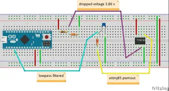
I am using the Arduino IDE to program the attiny85. I want to take an incoming analog reading, then based on that reading, output a specific PWM value. Here's my circuit:

my circuit

and here's my code:

// to run on attiny85

const byte pwmPin = 0;
const byte analogInPin = A2;

void setup() {
  pinMode(pwmPin, OUTPUT);
}

void loop() {
  int analogIn = analogRead(analogInPin);
  analogWrite(pwmPin, analogIn);
}

should be very simple- I have no problems uploading code to the attiny85, and no problems with simple tests like outputting a specific PWM value (not based on the analog read). but when I try to combine the two- read, then write that value, I can't seem to get things to work. In this circuit for example- I get a reading of 1023 (5v) on the arduino micro- instead of a reading of ~ 790 (3.85v) which is what I should expect. I've used a multimeter to verify the voltages in this circuit- so I think I must either be doing something wrong with my expectations of how to wire up or program the attiny85.

Peter Bloomfield
  • 10,932
  • 9
  • 47
  • 87
GradeSchool
  • 99
  • 1
  • 1
  • 4
  • 1
    A schematic of your circuit would probably be more helpful than an implementation schema with a breadboard. Do you have such a schematic? If yes, add it to your question. – jfpoilpret Mar 09 '14 at 18:58
  • I don't see any clock (quartz or ceramic resonator) for your ATtiny, is this normal? – jfpoilpret Mar 09 '14 at 19:05
  • @jfpoilpret yeah you have a few choices for using the internal clock. – sachleen Mar 09 '14 at 19:06
  • Did you try to add a short delay in your loop? What may happen is that your loop is running too fast, and each new analogWrite() call would "reset" the PWM of the pin, making it always up (no time to use PWM). I would try delay(1000) for a start. – jfpoilpret Mar 09 '14 at 19:11
  • Did your multimeter read 3.85v after the low pass filter? (so right on the Micro's input pin) – sachleen Mar 09 '14 at 19:12
  • 1
    i needed to re-range the input to 8 bit. analogIn = map(analogIn, 0, 1023, 0, 255); – GradeSchool Mar 09 '14 at 20:33
  • it works fine. btw i am using the internal 8mhz - attiny85. also using arduino-tiny core. thanks for all your suggestions. – GradeSchool Mar 09 '14 at 20:35
  • just to clarify - the adc input on the attiny85 is 10bit. the pwm output is 8bit. thus the map(). – GradeSchool Mar 09 '14 at 20:36
  • 2
    @GradeSchool It would be helpful if you could write your solution as an actual answer, so that future visitors can find it more easily. Thanks! – Peter Bloomfield Mar 09 '14 at 20:54
  • i tried to do that, but this site won't let me for like 8 more hours. i will do so as soon as i can. – GradeSchool Mar 09 '14 at 21:08
  • Could you throw in some capitals in your text to improve readability? Also a proper circuit diagram, rather than a wiring diagram would help a lot. – jippie Mar 09 '14 at 22:02

2 Answers2

8

Analog read is 10-bits (2^10 = 0-1023 range), analog write is 8-bits (2^8 = 0-255 range). Ditch the lower two bits of the result either by doing:

analogIn = analogIn >> 2;

which can be shortened to:

analogIn >>= 2;

Or you can use the rather complex map function:

analogIn = map( analogIn(0, 1023, 0, 255) )
Ricardo
  • 3,370
  • 2
  • 24
  • 53
Cybergibbons
  • 5,350
  • 7
  • 33
  • 51
4

i needed to re-range the 10bit input to 8 bit for the pwm out.

// to run on attiny85

const byte pwmPin = 0;
const byte analogInPin = A2;

void setup() {
}

void loop() {
  pinMode(pwmPin, OUTPUT);
  int analogIn = analogRead(analogInPin);
 analogIn = map(analogIn, 0, 1023, 0, 255);
 analogWrite(pwmPin, analogIn);
}
GradeSchool
  • 99
  • 1
  • 1
  • 4
  • 1
    the map function takes a lot of clock cycles compared to the bitshift describes in Cybergibbons' answer. – TheDoctor Mar 12 '14 at 12:55