9

I have a 1602 LCD screen that works fine on its own. However I wanted to free some pins by using an I2C / IIC LCD controller I purchased separately.

While the controller seems to be communicating with my Arduino UNO on the right address, I cannot get text to display. By default (no code) it seems the LCD will have 1 line of 16 solid "squares". When using address 27 in my code, the LCD will change to 2 lines of 16 squares (see photo below). The code also calls for the backlight to flash 3 times, which works. However I cannot get anything but 2 lines of squares. (Full code is at the bottom of this question).

I'm using the LiquidCrystal_I2C library by F Malpartida, which seems to be commonly used.
Is there a better library I should be using?

I'm wondering whether it's just the wrong pins being used in the code. All sketches I see online use the following pins:

//                    addr,en,rw,rs,d4,d5,d6,d7,bl,blpol
LiquidCrystal_I2C lcd(0x27, 2, 1, 0, 4, 5, 6, 7, 3, POSITIVE);
// Set the LCD I2C address

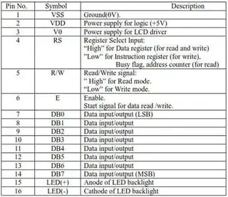
But all of the 1602 LCDs I see online have the same pins as mine, as you can see in my photo below:

I2C LCD Controller

These pins seem to be standard:
1602 LCD Pinout

To further confuse me, the pins on the LCD board start with 1 on the left, yet the default code's pins seem to start with 0! So I tried changing the code's pins to the numbers on the LCD board. The LCD no longer changes to 2 lines of squares and no longer blinks the backlight. I then tried subtracting 1 from each pin (to start from 0), same result. I then tried used the default pins minus 1, same result. Thus the default pins are somehow more correct?! What am I doing wrong?

Has anyone else gotten one of these I2C controllers to work for them, and if so, how?

Full code:

/* YourDuino.com Example Software Sketch
 16 character 2 line I2C Display
 Backpack Interface labelled "YwRobot Arduino LCM1602 IIC V1"
 terry@yourduino.com */

/*-----( Import needed libraries )-----*/
#include <Wire.h>  // Comes with Arduino IDE
// Get the LCD I2C Library here: 
// https://bitbucket.org/fmalpartida/new-liquidcrystal/downloads
#include <LiquidCrystal_I2C.h>

/*-----( Declare objects )-----*/
// set the LCD address to 0x27 for a 20 chars 2 line display
// Set the pins on the I2C chip used for LCD connections:
//                    addr, en,rw,rs,d4,d5,d6,d7,bl,blpol
LiquidCrystal_I2C lcd(0x27, 2, 1, 0, 4, 5, 6, 7, 3, POSITIVE);  // Set the LCD I2C address

void setup()   /*----( SETUP: RUNS ONCE )----*/
{
  Serial.begin(9600);  // Used to type in characters
  lcd.begin(16,2);   // initialize the lcd for 16 chars 2 lines, turn on backlight

// ------- Quick 3 blinks of backlight  -------------
  for(int i = 0; i< 3; i++) {
    lcd.backlight();
    delay(250);
    lcd.noBacklight();
    delay(250);
  }
  lcd.backlight(); // finish with backlight on  

//-------- Write characters on the display ------------------
// NOTE: Cursor Position: (CHAR, LINE) start at 0  
  lcd.setCursor(0,0); //Start at character 4 on line 0
  lcd.print("Hello, world!");
  delay(1000);
  lcd.setCursor(0,1);
  lcd.print("HI!YourDuino.com");
  delay(8000);  

// Wait and then tell user they can start the Serial Monitor and type in characters to
// Display. (Set Serial Monitor option to "No Line Ending")
  lcd.clear();
  lcd.setCursor(0,0); //Start at character 0 on line 0
  lcd.print("Use Serial Mon");
  lcd.setCursor(0,1);
  lcd.print("Type to display");  

}/*--(end setup )---*/

void loop()   /*----( LOOP: RUNS CONSTANTLY )----*/
{
  {
    // when characters arrive over the serial port...
    if (Serial.available()) {
      // wait a bit for the entire message to arrive
      delay(100);
      // clear the screen
      lcd.clear();
      // read all the available characters
      while (Serial.available() > 0) {
        // display each character to the LCD
        lcd.write(Serial.read());
      }
    }
  }

}/* --(end main loop )-- */
Bort
  • 397
  • 2
  • 6
  • 18
  • Did you remember to add the pullups? – Ignacio Vazquez-Abrams Dec 31 '14 at 19:08
  • @Ignacio, Can you elaborate? I'm only using 4 pins total. A4 and A5 for SDA and SCL respectively. 5V+ and GND for the controller. – Bort Dec 31 '14 at 19:12
  • 1
    http://electronics.stackexchange.com/questions/102611/what-happens-if-i-omit-the-pullup-resistors-on-i2c-lines – Ignacio Vazquez-Abrams Dec 31 '14 at 19:46
  • 1
    Probably not the problem, but have you tried adjusting the contrast using the potentiometer? The numbers in the code refer to which pin on the PCF8574 chip is connected to which pin on the lcd board. P3 on the I2C board is evidently connected to the backlight pin on the LCD. But I think the other pins are wrong somehow. Try using a multimeter to see where the P0-P7 pins of the PCF8574 go to which pins on the lcd header. – Gerben Dec 31 '14 at 20:54
  • @IgnacioVazquez-Abrams, although the pullups should be built into the controller, I tried adding them manually to no avail. – Bort Dec 31 '14 at 22:21
  • @Gerben, I adjusted the trimmer already and it's either full blocks or nothing at all. There are two circular plastic blobs on the bottom of the LCD board. I cannot actually see any ICs. I don't think I have any way to see or measure the pins of the PCF8574 because there are only 8 contacts on the back of the board, but the PCF8574 has 16. I'm ready to blame the controller. – Bort Dec 31 '14 at 22:23
  • 2
    Although it may not be the issue, you should pay attention to the soldered pin headers on the LCD, from the picture they appear to not completely cover the copper around the hole; I would try to improve these solder points first. – jfpoilpret Jan 01 '15 at 00:13
  • The PCF8574 is the chip on the I2C interface board, not on the lcd board. Please re-read my comment, it see if it makes sense now. Otherwise, let me know. – Gerben Jan 01 '15 at 14:28
  • 1
    @Gerben, derp. I tested the chip with a multimeter, however I am still completely confused. Pins 9-12 on the chip correspond to D4-D7 on the lCD. Pin 6=E, 5=RW, and 4=RS. I cannot figure out what pin 7 actually is. Using those values gives me no response from the LCD again. Also, am I supposed to subtract 1 from those pins? Because again, all the default codes out there have pin 0=RS. But that can't be, because the first pin on the chip is A0 (address). Basically, changing any single pin will either kill the backlight response or stop the 2nd row from showing the block characters. – Bort Jan 01 '15 at 19:42
  • The numbers 0-7 in the code refer to the P0-P7 pins on the PCF8574. If you look at the datasheet, P0 is on pin 4, P1 on 5, P2 on 6, P3 on 7, P4 on 9, P5 on 10, P6 on 11, P7 on 12.

    So in your case, P0 goes to RS, P1 to RW, P2 to E P3 to backlight, P4-P7 to D4-D7. So your numbers in the code you've given were correct (i.e. LiquidCrystal_I2C lcd(0x27, 2, 1, 0, 4, 5, 6, 7, 3, POSITIVE);).

    So that wasn't the problem. Try reseating the headers in the breadboard, as there could be an improper connection. Also resolder the header on the LCD, as they aren't great solder joint (to little solder).

    – Gerben Jan 01 '15 at 22:15
  • I have the very same problem. I2C scanner found the display. I also traced the connections and got the same pin setup. I can turn on/off the display - it has a cursor but no text. No clue what's going on. Did you solve it eventually? – tcurdt Oct 24 '15 at 00:39
  • @tcurdt I've had no success with those particular components. I found that I can buy a 1602 LCD with an I2C controller already attached for nearly the same price, and that worked for me. – Bort Oct 24 '15 at 16:50
  • Just got into this. Backlight control works, no text output on display. – zgoda Jun 02 '16 at 09:45
  • It's a good idea to check what library and code the seller told to use, most of them provide samples. – Avamander Aug 19 '16 at 19:25
  • As far as I know, the pull-up resistors should be integrated with the display. Did you try different addresses? I have a similar one, which works on address 0x3F. Maybe this helps. – engineer Dec 31 '14 at 20:09
  • The board was sold as "address 27", and 27 is the only address that responds at all. It's actually customizable by soldering the A1 A2 and A3 pins just above the trimming pot seen in the photo. – Bort Dec 31 '14 at 22:19

3 Answers3

3

First of all, it looks like these wires aren't properly connected:

enter image description here

I haven't disassembled a female jumper before, so that might not be the issue. However, it seems likely that this could be a cause.

Also, you need to adjust the contrast by turning that trimmer (the blue thing that looks kinda like it has a screw in it). LCDs will either display nothing, a washed out version of the text, or blue boxes if the contrast is not set correctly. This is probably the cause.

Anonymous Penguin
  • 6,285
  • 10
  • 32
  • 62
  • The jumpers are like that only because I moved the board for the photo. Also I adjusted the trimmer already and it's either full blocks or nothing at all. – Bort Dec 31 '14 at 22:10
3

I bought the SainSmart 20x04 and I also had to change the address to 0x3F. My backlight jumper was missing, that little header at the right of the I2C board provides the backlight power. Some code I found included this:

lcd.setBacklightPin(BACKLIGHT_PIN,POSITIVE);
Ricardo
  • 3,370
  • 2
  • 24
  • 53
Ed Kimble
  • 31
  • 1
-1

Change this code:

LiquidCrystal_I2C lcd(0x26, 2, 1, 0, 4, 5, 6, 7, 3, POSITIVE);

To this:

LiquidCrystal_I2C lcd(0x26, 2, 1, 0, 4, 5, 6, 7, 8, POSITIVE);

(The argument before "POSITIVE" is changed from a 3 to an 8)

Anonymous Penguin
  • 6,285
  • 10
  • 32
  • 62
oz1ayw
  • 9
  • 1